

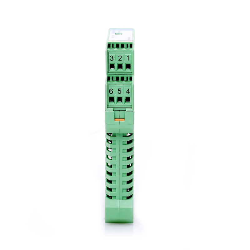


 1input/2outputs
Relay
Dry contact/proximity switch
24VDC
Terminal Power Supply
1input/2outputs
Relay
Dry contact/proximity switch
24VDC
Terminal Power Supply


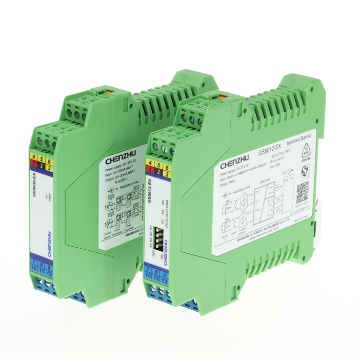
| Product Name | GS5111-EX Isolated Barrier |
| Number of channels | 1 input/2 outputs |
| Supply voltage(Ue) | 20~35V DC |
| Input signal | Switch or NAMUR Proximity Detector |
| Output signal | Relay |
| Ex-marking | [Ex ia Ga]IIC |
| Field apparatus | Dry contact or DIN19234 standard NAMUR proximity switch inpu t field devices (including the intrinsically safe type pressure switc h, temperature switches, liquid level switch). |


| Number of channels | 1input/2outputs |
| Dielectric strength | Between non-intrinsically safe part and intrinsically safe part≥2500VAC,Between power supply part and non-intrinsically safe part≥500VAC |
| Response time | ≤10ms |
| Insulation resistance | Between non-intrinsically safe part and intrinsically safe part≥100MΩ,Between power supply part and non-intrinsically safe part≥100MΩ |
| Electromagnetic compatibility | According to IEC 61326-1(GB/T 18268) |
| EX marking | [Ex ia Ga]ⅡC [Ex iaD] |
| Weight | Approx 100g |
| Field apparatus | Dry contact or DIN19234 standard NAMUR proximity switch input field devices (including the intrinsically safe type pressure switch, temperature switches, liquid level switch) |
| Suitable location | zone 0;zone 1;zone 2;IIA;IIB;IIC;T4~T6 |
| Input signal | Switch or NAMUR Proximity Detector |
| Open circuit voltage | ≈8V |
| Short circuit current | ≈8mA |
| Drive capability | 250V AC,2A or 30V DC,2A |
| Load type | resistive load |
| Output signal | Relay |
| Supply voltage(Ue) | 20~35V DC |
| Power protection | Reverse protection of power supply |
| Current consumption | (at 24Vdc supply,output energized)≤40mA |
| Power supply mode | Independent power supply |
| Power connecting mode | Terminal |
| Depth | 114.5mm |
| Height | 99.0mm |
| Width | 17.5mm |
| Material | PA |
| Degree of protection | IP20 |
| Flammability rating | UL94/V0 |
| Colour | green |
| Approvals | NEPSI |
| NEPSI | [Ex ia Ga] IIC Comply with standard: GB 3836.1、GB 3836.4、GB 3836.20 [Ex iaD] Comply with standard: GB 12476.1、GB 12476.4 |
| Max. r.m.s. a.c. or d.c. voltage Um | 250V |
| Max.output voltage Uo | 10.5V(7,8) |
| Max.output current Io | 14mA(7,8) |
| Max.output power Po | 37mW(7,8) |
| IIC Max. external inductance Lo | 165mH(7,8) |
| IIC Max. external capacitance Co | 2.4μF(7,8) |
| IIB Max. external inductance Lo | 495mH(7,8) |
| IIB Max. external capacitance Co | 16.8μF(7,8) |
| IIA Max. external inductance Lo | 1000mH(7,8) |
| IIA Max. external capacitance Co | 75.0μF(7,8) |
| Electrical fast transient/burst immunity | According to:IEC 61326-1;Class A |
| Surge immunity | According to:IEC 61326-1;Class B |
| Radiated,radio-frequency,electromagnetic field immunity | According to:IEC 61326-1;Class A |
| Electrostatic discharge immunity | According to:IEC 61326-1;Class A |
| Immunity to conducted disturbances, induced by radio-frequency fields | According to:IEC 61326-1 |
| Ambient temperature | -20℃~+60℃ |
| Storage temperature | -40℃~+80℃ |
| Relative humidity | 10%~90% |
| Environmental requirements | The air should not contain any medium corrupting the coat of chrome,nickel and silver.Moreover,violent quiver and impact or any cause of electromagnetic induction (such as big current or spark,etc.)must be avoided when using |
| Conductor cross section solid range | 0.5~2.5mm² |
| Conductor cross section flexible range | 0.5~2.5mm² |
| Conductor cross section AWG min. | 12 |
| Conductor cross section AWG max. | 24 |
| Stripping length | 8mm |
| Screw thread | M3 |
| Connection method | Screw connection |
| Tightening torque min. | 0.5 Nm |
| Tightening torque max. | 0.6 Nm |
| Mounting type | DIN35mm |
| Input and output characteristics | If input > 2.1mA, output relay is energized, with yellow LED ON. If input < 1.2mA, output relay is de-energized,with yellow LED OFF. |
| Switch setting function | Switch(I),K2 and K4 must be set to OFF state, no line fault (breakage, short circuit) detection; When using line fault (breakage, short circuit) detection function, resistors must be fitted, 22kΩ in parallel with switch, 680Ω in series with switch, see Switch (II), K2 and K4 set to ON state. |
Select All
 Select All